


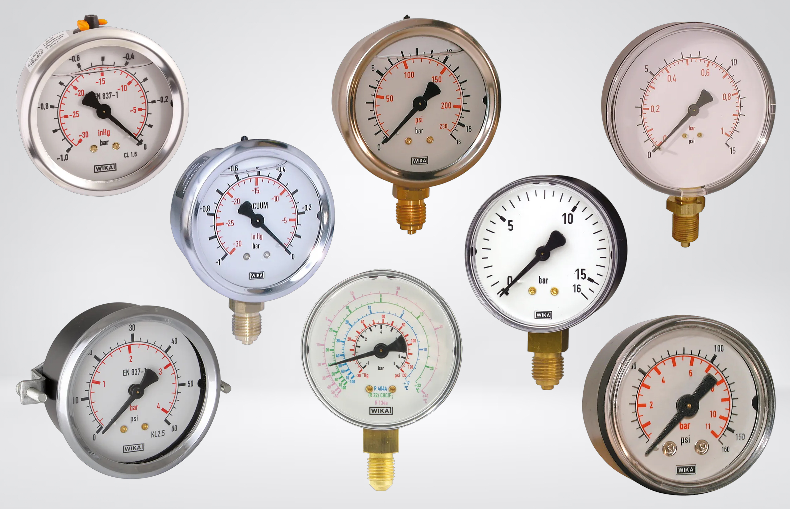
A hydraulic pressure gauge may be a relatively small component, but it often provides the first indication that something within a system is not operating as intended. Engineers rely on it when setting relief valves, assessing pump performance, checking actuator loads and investigating restrictions or pressure loss. If the gauge is poorly specified, the reading can be difficult to interpret or, worse, confidently misleading.
Matching the thread and choosing a scale that reaches the system’s maximum pressure is not enough. Hydraulic gauges are exposed to pressure pulsation, transient spikes, mechanical vibration and fluid temperatures that can shorten instrument life significantly. A gauge may appear to operate below its maximum scale while still being damaged by pressure events that occur too quickly for the pointer to show.
WIKA offers mechanical, liquid-filled, stainless steel and electronic pressure-measurement options for hydraulic applications. The right choice depends on what the instrument needs to tell you, how the pressure behaves and where the gauge will be installed.
This guide explains how to select the appropriate WIKA gauge for a hydraulic system, including pressure range, accuracy, construction, connection type, mounting and protection against demanding operating conditions.
Why Pressure Gauge Selection Matters in a Hydraulic System
A pressure gauge only becomes useful when its reading accurately reflects what is happening at the measuring point. Maintenance teams use gauges to confirm pump output, set relief valves, compare pressures across components and investigate why an actuator is moving slowly or failing to produce the expected force. On a production machine, a gradual change in pressure can also provide early warning of wear, restriction or incorrect adjustment.
An unsuitable gauge can send fault-finding in the wrong direction. If vibration causes the pointer to oscillate across a wide section of the scale, an engineer may be unable to distinguish normal pressure variation from a genuine system problem. If the selected range is unnecessarily high, smaller changes may be almost invisible. A damaged or inaccurate gauge can suggest that the pump, valve or actuator is at fault when the measurement itself is unreliable.
Hydraulic pressure is rarely perfectly steady. Pump operation, directional valve changes, actuators reaching the end of their travel and relief valves opening can all create pulsation or short pressure spikes. These events may load the internal measuring mechanism even when the pointer appears to show an acceptable working pressure. Repeated exposure can shift the calibration, prevent the pointer from returning to zero or cause complete instrument failure.
The location of the gauge matters as well. An instrument mounted directly to a pump or unsupported pipework may experience considerably more vibration than one installed on a panel or connected remotely. Fluid temperature, outdoor exposure, corrosive surroundings and the risk of physical impact can also determine whether a standard case is adequate or a more robust stainless steel construction is justified.
For this reason, pressure range should never be considered in isolation. A reliable WIKA gauge specification must account for the pressure profile, operating environment, hydraulic fluid, required accuracy and mounting arrangement. Getting these points right produces a reading that engineers can trust and reduces the likelihood of treating gauge failure as a recurring maintenance expense.
A Practical WIKA Gauge Selection Checklist
Before ordering a WIKA pressure gauge, gather the information below. Providing a complete specification reduces the risk of receiving an instrument that fits the port but performs poorly once the machine is running.
- What is the normal operating pressure?
Use the pressure seen during a complete machine cycle, not simply the nominal pump rating. - What is the maximum expected pressure?
Include the relief-valve setting, stalled actuator pressure and any known start-up or load-related peaks. - Are pulsation or pressure spikes present?
Note whether the pointer oscillates, failures occur repeatedly or valves and actuators operate rapidly. - Is the gauge exposed to mechanical vibration?
Identify whether it will be mounted directly to a pump, manifold, mobile machine or unsupported pipework. - What fluid is being measured?
Provide the exact hydraulic fluid where possible, especially for water-glycol, synthetic and fire-resistant fluids. - What are the fluid and ambient temperatures?
Consider the temperature at the measuring point as well as the wider operating environment. - What level of accuracy is required?
Distinguish between general monitoring, maintenance diagnosis, component adjustment and documented testing. - Which dial size is appropriate?
Account for viewing distance, available space and the smallest pressure change that operators need to recognise. - Is a bottom or rear connection required?
Check the existing pipework, mounting panel and intended viewing direction. - What is the connection standard and size?
Confirm whether the port is BSPP, BSPT, NPT, metric, SAE or another type, along with the sealing method. - Which wetted-part materials are suitable?
Do not assume that a stainless steel case means the measuring system is also stainless steel. - Will the gauge be mounted directly or remotely?
Consider vibration, heat, accessibility, physical protection and the support available for connecting pipework. - Is local indication sufficient?
If pressure must be recorded, transmitted to a PLC or used to trigger an action, consider a WIKA transmitter or electronic pressure switch. - Are protective accessories required?
Determine whether the installation needs a snubber, restrictor, isolation valve, mounting bracket, adaptor or hydraulic test point. - Is a calibration certificate needed?
Confirm this before ordering because it may affect the product selection, cost and delivery time.
If some of these details are unavailable, avoid copying the failed gauge automatically. Its specification may be the reason it did not provide a stable reading or acceptable service life. Hoses Direct can help identify the missing information and match the WIKA instrument and associated hydraulic components to the actual application.
Choosing Between the Main WIKA Pressure Measurement Options
The correct instrument depends on how the pressure information will be used. A mechanical gauge is usually the most practical option for routine local indication, while testing, remote monitoring and automated control require different capabilities.
| Instrument type | Best suited to | Main advantage | Key consideration |
| Mechanical dry gauge | Stable pressure and general local monitoring | Simple, immediate indication without a power supply | Pointer movement in vibrating or pulsating systems |
| Liquid-filled gauge | Hydraulic power units, pumps and vibrating machinery | Improved readability and reduced movement wear | Filling does not protect against severe pressure spikes |
| Stainless steel gauge | Corrosive environments or specialist fluids | Greater environmental and material resistance | Confirm whether the wetted parts are also stainless steel |
| Digital pressure gauge | Testing, commissioning and precise adjustment | Clear numerical reading and useful diagnostic functions | Power supply, response rate and environmental protection |
| Pressure transmitter | PLC input, remote monitoring and data logging | Continuous electrical output | Signal type, supply voltage and electrical connection |
| Electronic pressure switch | Alarms, interlocks and machine control | Pressure-dependent switching with local display options | Switching logic, output type and response behaviour |
For a permanently mounted gauge on a typical hydraulic power unit, a liquid-filled mechanical WIKA instrument is often the most practical starting point. It provides a clear local reading and copes better with the vibration and pulsation commonly found around pumps and manifolds.
A dry gauge may still be appropriate where pressure is stable, and the instrument is mounted away from vibration. Specifying liquid filling in every application is unnecessary if the operating conditions do not require it.
Digital gauges are more useful when the pressure must be adjusted closely, or small changes need to be compared during testing. If the value must be displayed elsewhere, recorded continuously or used by the control system, a WIKA pressure transmitter provides the appropriate electrical signal. Where pressure must directly trigger an alarm or machine action, an electronic pressure switch is usually the better fit.
Some systems benefit from more than one instrument. A machine may use a transmitter for PLC monitoring while retaining a mechanical gauge for quick local checks during maintenance. The devices should then be selected to provide complementary information rather than assuming one instrument must perform every function.
Why Buy WIKA Gauges from Hoses Direct?
The main risk when buying a hydraulic pressure gauge is not obtaining a poorly made instrument. It is obtaining a good instrument with the wrong range, connection, materials or dynamic-pressure capability for the system.
Hoses Direct supplies hydraulic components as complete working systems, so gauge selection can be considered alongside the hose, fittings, test points, adaptors and valves surrounding it. This is particularly useful when the existing instrument has failed repeatedly or its connection cannot be identified confidently.
The technical team can help customers confirm:
- The appropriate pressure range for the working and relief pressures
- Whether vibration or pulsation justifies a liquid-filled gauge
- The required accuracy and dial size
- BSPP, BSPT, NPT and other process connections
- Bottom-entry or rear-entry mounting
- Compatibility between the fluid and wetted parts
- Suitable adaptors, test points, isolators and snubbers
- Whether a mechanical gauge, transmitter or pressure switch is required
- Calibration certificate requirements
Buying the gauge and its connecting components from the same supplier also reduces compatibility problems. Adaptors and test fittings must have suitable pressure ratings and sealing methods; they should not be selected simply because the threads appear to fit.
Hoses Direct can supply WIKA mechanical pressure-measurement products alongside electronic options such as A-10 pressure transmitters and PSD-30 pressure switches with displays. This allows the specification to follow the measurement task, whether the requirement is a straightforward local indication, a signal for a PLC or pressure-dependent machine control.
For a direct replacement, provide the WIKA model or part number and clear photographs of the dial, connection and label. For a new installation or recurring failure, include the normal pressure, relief setting, fluid, temperature, thread, mounting position and details of any vibration or pointer movement. That information gives the technical team a reliable basis for recommending the right instrument rather than simply matching the visible features of the old gauge.
Get in touch with the team today using the below to discuss your requirements.
Email: [email protected]
Phone: 0333 6000 501